DST Digital Servo Tester / LCD Tachometer
DST V 3.24
Digital Servo Tester / Tachometer, Four in one -- 16F84A
for DST V 4.X visit here
¡@
===== Acknowledgements 2010/01 ==================
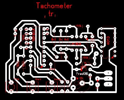
Fred <micowave@clix.pt> from Azores islands, Portugal. offer PCB layout for both V3.X and V4.X.
Here is the V3.X . Download lay file DST_Fr84.zip

=================================================
V3.24 update: FIX bug, when doing receiver testing may crash at 1500uS. thanks to "ysniwo" from Taiwan who reported the bug.¡@
V3.23 Update
Due to some strange LCD modules (C1602B-xxx) can't operate normally, but display two black line, with the V3.22. I do some modification to make the program fit all LCD modules I have had.
=================================================
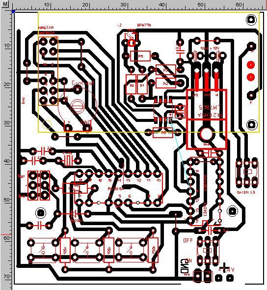
Andrey offer a new layout here with LM358 front-end
Thanks to Andrey again. The .lay file can open by "Sprint Layout" program
=================================================
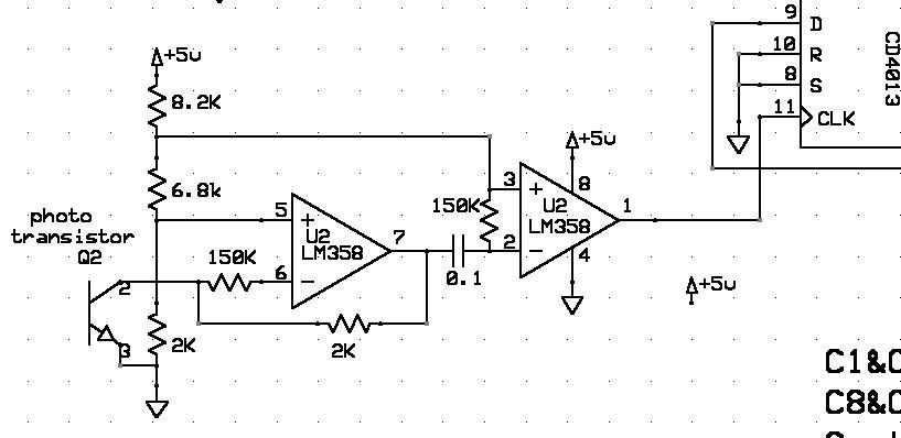
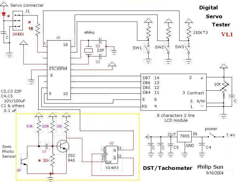
The Hardware V1.1C DST.sch with LM358 front-end, others same as V1.1
For higher sensibility, the front end of Tachometer, use a LM358 IC instead of 2SC945.
This circuit can read scintillation of scintillant light, easily.
¡@
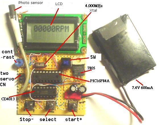
Hardware V 1.1 with 2SC945 front-end
=================================================
Digital servo tester (DST)
Full digitize, 10 uS / step, 20mS / frame, have five test modes:
1. Manual mode
the PWM pulse width range from 1000uS~ 2000uS, 10uS/step with one touch neutral point (1500uS).
2 .Slow mode
take 10 second from 1000 to 2000 and reverse too, auto process 2 times
3. Fast mode
Jump between 1000 and 2000 every 0.5 second, auto process 5 times
4 .Mid mode
take 2 second from 1000 to 2000 and reverse too, auto process 5 times
5. Random mode
Random Jump every 0.3 second, auto process 20~30 times
-------------------------------------------------------------------------------------------------
Receiver tester (REC_T )
Function: read out receiver's output PWM width, and test the sticks of transmitter.
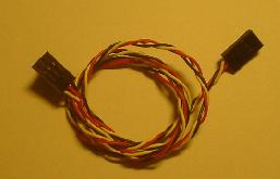
For this test, you need a connecter like this with two female end.
You can connect two ordinary servo cable to get this.
¡@
--------------------------------------------------------------------------------------------
Speed Controller Tester (SCT)
The PWM pulse width range from 1000uS~ 2000uS, 10uS/step with one touch stop (1000 uS)..
The initial pulse width is 1000 uS.
--------------------------------------------------------------------------------------------
LCD Tachometer
range from 100 RPM to 99900 RPM, 100 RPM resolution for 2 to 5 blades propeller
accuracy 100~ 10000 +- 100 RPM, 10000~99900 +- 1% , refresh rate 0.6 second / time
=================================================
Operation Manual: here
DIY tips:
Remember to connect CD4013 pin 3,4,5,6,7,8,10 to GND, pin 14 to VCC, and a 0.1 uF between pin 7 & 14
For more detail & DIY , see the LED Tachometer for ref.
More picture about the prototype pic1 pic2 pic3
=================================================
1. The 5 mm phototransistor is L-51P3C . any 3~5 mm phototransistor work with hardware V1.1C
2. Three lead phototransistor is OK. just let the "B" unleaded.
3. LCD module is WH0802A from WINSTAR, almost any brand will do, even a 16*2. the pin count are all the same.
=================================================
16F84A.ASM V3.24 16F84A.HEX V3.24
======================================================================================¡@
You MAY duplicate, modify, give away or sell the original files in the web site or anything you derive from it.
ATTENTION : It is your own responsibility, if any damage cause by using the web site.
Philip Sun / TAIWAN
copyright 2004