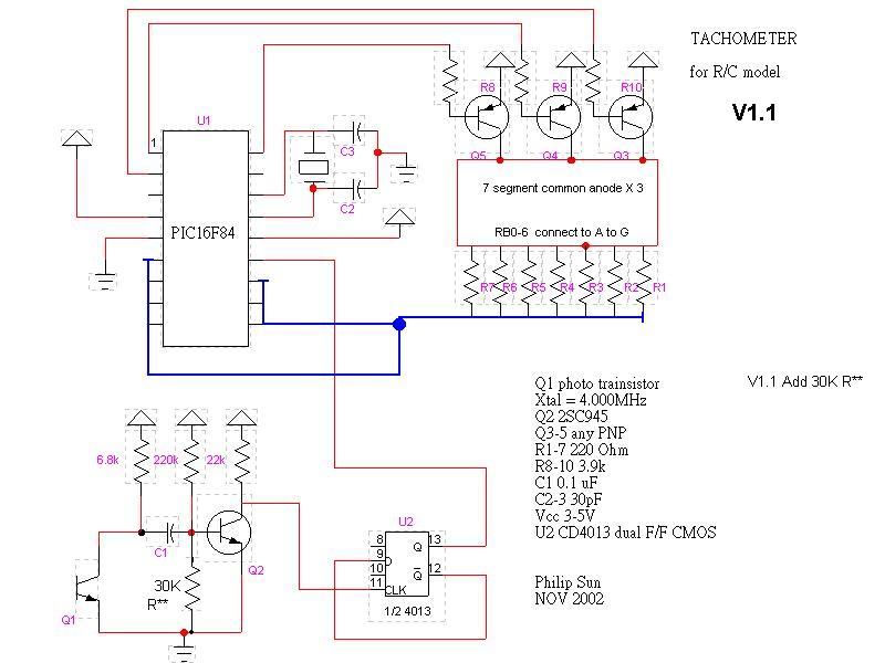
TACHOMETER PIC16F84
for R/C model V1.2 update 10/2004
last update 9/2009
Acknowledgements 2009/9 ========================
Richard <cfiftycc@gmail.com> help edited this page,
corrected grammar and add comments.
Richard also design / provide PCB for this project, if you need the PCB please
contact Richard.
Thank you Richard !!!
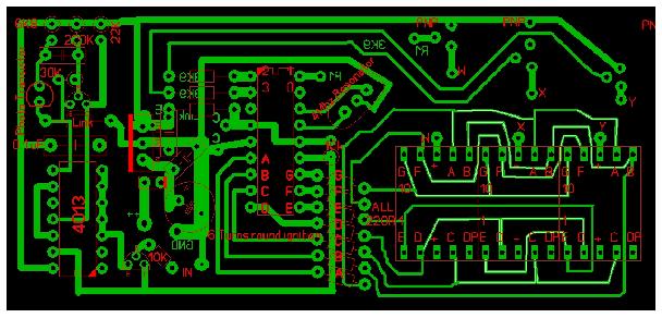
Download the layout file ( Sprint Layout format )
============================================
This easy to build tachometer can read from 100 RPM to 99,900 RPM +- 100 RPM .
The key point in this design is using hardware to do a "divide by two", It also supplied a duty rate 50/50 square wave for software to detect if input changing. without take the risk to loss any input when it doing refresh display.
The 4013 "divide by two" d-type flip flop compensates the two blades propeller which sends two pulses per revolution.
Input pulses are counted inside a 0.6 second window. They will equal RPM * 100.
A 1 second window might seem the obvious choice---but----THIS WILL GIVE YOU
HERTZ----CYCLES PER SECOND.
RPM is Cycles per minute!! 60 times bigger…
============================================
1020 RPM = 17 Hertz/Sec X 60 sec
So, just count the input Hertz for 0.6 seconds… 17 x 0.6 = 10 (counting windows
closes during the 11th pulse)
The scale is RPM x 100 so 10 x 100 = 1000 RPM. 20RPM is the error.
At least you know if you have 900, 1000 or 1100 RPM.
This is 20/1000 = 1/50 or 2% error at 1020RPM
============================================
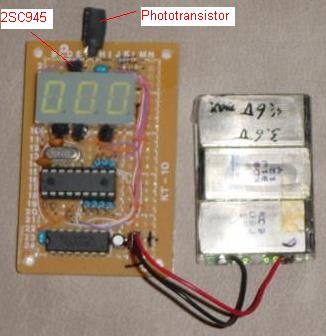
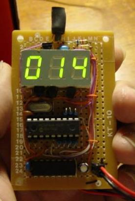
When use this tachometer, the direction & brightness of light is critical.
Put the 5 mm Phototransistor as close to 2SC945 as possible, ref. the picture above.
Remember to connect CD4013 pin 3,4,5,6,7,8,10 to GND, pin 14 to VCC, and a 0.1 uF between pin 7 & 14
What the Tachometer does is count revolutions per minute, -- RPM.
There are two ways to determine RPM.
Method 1. open input, count input pulses for
1 second then multiply the pulse count by 60. OR, open input . count input
pulses for 0.6 second. Final count will be RPM x 100.
**NB** The software counting window will close during a pulse. So there will
always be a rounded count.
IF you want use method 1, beware, don't lose any input pulses before end of
counting.
Method 2. detect pulse cycle time using two pulses.
If you want method 2, the pulse cycle time varies from 0.6 S to 0.6 mS ( 100 -
99900 RPM )
============================================
At 1020RPM this is 17Hz which equals 58.8 mS. Then use the formula
"RPM= 60 sec / 58.8mS.
============================================
Either way you need a precise timer. This project uses Method 1.
To drive 7 segments LED display you have to refresh each character at least 30
times per second,. This requires other timer.
My first idea was to use PICC16C54 to do this job, because it is cheaper. but I
can not get +- 1% accuracy in all conditions. 16C54 does not have an interrupt,
the 16F84 has one.
With a 4 MHz X'tal every instruction needs 1 uS, I set pre-scale to 64,
after 75 interrupts (64* 75= 4.8 mS), refresh one character , after 125
character refreshes (4.8* 125= 600 mS ), the content of counter is the RPM *100.
The input pulse from the photo sensor may as narrow as several uS, it is hard
for the software to detect this narrow pulse without any loss. With the help of
CD4013, the input won't change phase ( from 0 to 1 or 1 to 0 ) within 0.6 mS.
Finally, put your photo sensor in a dark cylinder, to get rid of ambient light.
The program include configuration: OSC =XT, PWRT -- enable.
PIC16F84 ASM V1.2 TACHO.HEX V1.2
======================================================================================
You MAY duplicate, modify, give away or sell the original files in the web site or anything you derive from it.
ATTENTION : It is your own responsibility, if any damage cause by using the web site.
Philip Sun / TAIWAN
copy right 2004
