R/C Multi-Tester V4.20 / V4.35
Digital Servo Tester / Tachometer, Four in one
V4.35 - PIC16F88 / V4.20 - PIC16F628
===== 2010/07 ===== Open V4.20 codes and schema for 16F628
===== Acknowledgements 2010/01 ======================
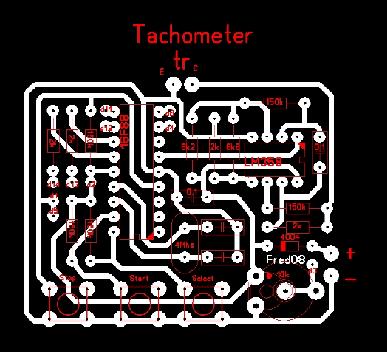
Fred <micowave@clix.pt> from Azores islands, Portugal. offer PCB layout for both V3.X and V4.X.
Here is the V4.X . Download lay file DST_Fr88.zip

===== Acknowledgements =============================
A 75 x 50 mm PCB, design by Glatt Wastl
from the Bavarian Alps.
fit the dimensions of the LCD module, pins to holes.
Thank you, Glatt Wastl !
===== Acknowledgements =============================
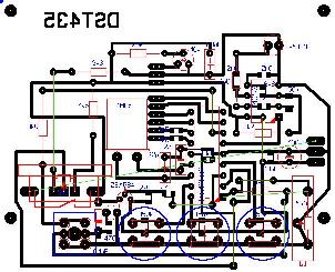
"Sprint-layout"
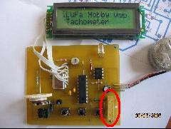
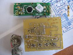
file of MT 4.X : Kolchnov Jan from Moscow contributed this file. and this are photos of his MT.Thank you, Jan ! deeply appreciate of your work.
===== Acknowledgements =============================
Another Sprint-layout contribute by Sergey Zhuravlev from Ostrogozhsk, Russia
( Sergey Zhuravlev use a pot to replace 39K ohm 1% resistor for
the voltmeter )


================================================
Download:
Schema .jpg (V1.6 / 16F88)
Schema .jpg (V1.2 / 16F628)
Schema .sch (V1.6 / 16F88)
================================================
Multi-Tester V4.35 Spec:
Tachometer :
Non-contact Digital Photo Tachometer
Servo tester:
Resolution 10 uS / step, 20mS / frame
6 test modes:
1. Manual mode
The PWM pulse width range from 1000uS~ 2000uS, 10uS/step with one touch neutral point (1500uS).
2 Knob
Analog knob input, around 850uS ~ 2150uS
3. Fast mode
Jump between 1000 and 2000 every 0.5 second, auto process 5 times
4. Middle mode
2 second from side to side, auto process 5 times
5. Slow mode
10 second from side to side, auto process 2 times
6. Random mode
Random Jump every 0.3 second, auto process 20~30 times
Speed controller tester:
2 test modes:
1. Manual mode
The PWM pulse width range from 1000uS~ 2000uS, 10uS/step with one-touch stop point (1000uS).
2 Knob
Analog knob input, around 850uS ~ 2150uS, depend
Receiver tester:
Measure Range 0.80mS ~ 2.20mS PWM
Voltmeter:
DC 0~20.0V / resolution 0.1V
================================================
FAQ:
1. What the purpose of the LED ?
The LED is indicator of Vcc Out to servo,
2. I notice the 2SA684 doesn't turn ON in Tacho mode. Could the 2SA684 be
program to turn on during Tacho mode or Receiver mode?
This could be useful when testing small park receiver like GWS nano or pico receiver.
If you need to power receiver, just add one more 3-pin
connector, with the pin2 connect to Vcc through one diode (like the V3.X
version) , or eliminate the 2SA468, at all
================================================
PIC16F88.ASM V4.35 PIC16F88.HEX V4.35
PIC16F628.ASM V4.20 PIC16F628.HEX V4.20
======================================================================================
You MAY duplicate, modify, give away or sell the original files in the web site or anything you derive from it.
ATTENTION : It is your own responsibility, if any damage cause by using the web site.
Philip Sun / TAIWAN
copyright 2005