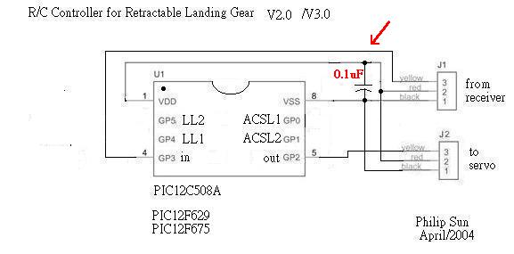
R/C Controller for Retractable Landing Gear V 3.1
with Anti-Collision Strobe Light & Landing Lights
PIC12C508A, 12F629 /675
V3.1
Someone experienced the motion angle become narrower, after connect with V3.0 controller. Because the program limit the PWM Pulse width range between 1.00~2.00mS. (Llimit & Rlimit in ASM files)
V3.1 extend the limit to 0.90~2.10mS (as GWS servo can operate safely), and this is a 4 second side to side version.
----------------------------------------------------------------------------
V3.0
The V3.0 is for those R/C controllers with "end point trim", such as Futaba FF9, JR 9X.
The V2.0 output has only two conditions, left limit (1 mS), or right limit (2 mS), it's good for those without "end point trim", such as ALING, an additional fifth channel for Futaba skysport4 or controllers without fifth channel, (you can control Retractable Landing Gear with joystick).
The V3.0 can output 101 different pulse width from 1.00mS to 2.00mS, 10uS @ step, and it's right & left end point are depend on your R/C controller.
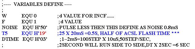
The ACSL1 & ACSL2 nominate flash half cycle is 0.5 second for V3.0, if you want to change it, modify the ASM file as follow:
The " T5 EQU H'19' means T5 = 25 (decimal), the 20mS is average time period that R/C controllers repeat the entire signal flame, but may vary. modify '19' as you want.
The time period for servo move from side to side also depend on this 20 mS time period, because the program use it to move steps, so 2 second will move 100 steps, and only 2 seconds from side to side is too fast. So , DTIME going to delay this. '03' means 2 seconds multiply by three, get 6 seconds, you may change this '03' as you want.
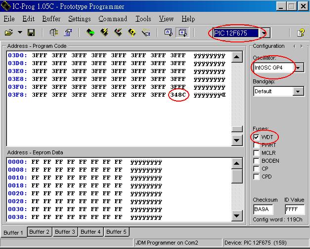
Program include configuration setup:
OSC = IntRC
WDT = enable
If PIC12F675, be careful, OSC=IntOSC GP4
--------------------------------------------------------------------
V 2.0
Friend say "need landing too", I think "why not". So we have V2.0 now.
I add Anti-Colliosion Strobe Light (ACSL1 & ACSL2) which flash alternative, every 0.6 (half cycle) and , of course, you may change this. Just change the T5 var. in the ASM file and re-assemble it to HEX
The Lading light 1 (LL1) active HIGH when gear down, the LL2 is invert of LL1, in case your gear is reverse. The loading current limit of these pins are 25mA@, please ref. the Multi-Function R/C Controller
Add these options need only few instructions, in ASM file I mark those with ***, and K5, K6 sections
Here is a testing video
---------------------------------------------------------------------
V 1.0
Is your R/C aircraft Retractable Landing Gear move too fast ?V1.0
I design this to make Retractable Landing Gear take 4 seconds to move from side to side.
This simple design use only one PIC12C508A
Program the PIC with the HEX file, and find an extended line for servo. Cut the extended line at center, make your welding work. Now you have all you need. Connect the extended line between receiver and servo, that's all.
If you don't like 4 seconds, the ASM file is for you. just change the <T2> value and loop delay in <k4> section. but make sure (T2* loop's uS)=1000 uS , because servo accept 1.5 mS +- 0.5 mS. and (T2 / 50) would be the time it take from side to side.
PIC12C508A ASM V3.1 PIC12C508A HEX V3.1
PIC12C508A ASM V3.0 PIC12C508A HEX V3.0
PIC12F629 ASM V3.0 PIC12F629 HEX V3.0
PIC12F675 ASM V3.0 PIC12F675 HEX V3.0
=================================================================================
You MAY duplicate, modify, give away or sell the original files in the web site or anything you derive from it.
ATTENTION : It is your own responsibility, if any damage cause by using the web site.
Philip Sun / TAIWAN
copyright 2004
