R/C Controller for Retractable Landing Gear
How it work ?
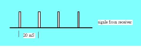
A normal control signal from receiver is a 1.5 mS (+- 0.5mS) plus pulse, repeat every 20 mS (variable), it's PWM. The servo rotate and stop at position correspond to the width. e.g. 1.0 mS pluse will put the servo rotate to right limit, 2.0 mS to left limit.

1. This microchip read the pulse, measure it's width, if less than 0.8 mS, treat it as noise and ignored, if between 0.8- 1.3 mS as low level, if large than 1.7mS as high level. (see MAIN section in the ASM code file)
2. A input level compare with the current status of servo, if input is low and servo at low side, next step is checking if High pass counter (HP) been decrease to zero..... (see HIGH & LOW section). After more than (T4) 9 same level pulses been detected, which pulses opposite to current status, will invert the status. this make sure possibility of error action is very low .
3. The most interesting part of the program is section OUTPUT. Use T1, TMR2 (timer 2), and a 5uS loop to make a 1.0 mS high level of output, after that use TMR1, which value between 0 - 200 (T2) to make additional high level width, so the real output will be high pulse between 1-2 mS. When the status invert (servo rotate) , the TMR1 increase/decrease one, every time it been check, and it's about 20 mS (decide by your remote controller, which compose the PWMs), so it take about 4 seconds from 0 <-> 200.
======================================================================================¡@
You can duplicate, modify, give away or sell the original files in the web site or anything you derive from it.
ATTENTION : It is your own responsibility, if any damage cause by using the web site.
Philip Sun / TAIWAN
copy right 2004
¡@